How to bond module frames and structures, when an external lightning protection system is needed, how to keep the separation distance, and where Type 1 and Type 2 surge protective devices belong — following IEC 62305 and IEC 60364-7-712.
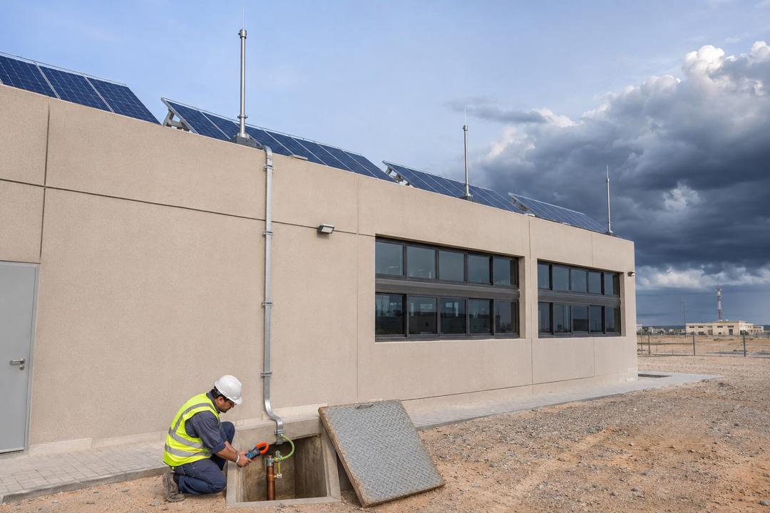
Earthing in a PV system does three different jobs, and it helps to keep them apart. Protective earthing and equipotential bonding make sure that a fault cannot leave a touchable metal part — a module frame, rail or inverter enclosure — at a dangerous voltage. Functional earthing, where an inverter or module technology requires it, ties one pole of the DC circuit to earth. Lightning protection gives a direct strike a safe path to ground and limits the surges induced in cables by nearby strikes. IEC 60364-7-712 covers the first two for PV installations; the IEC 62305 series covers lightning.
All exposed metal of the array should be bonded together and to the main earthing terminal of the installation: module frames through listed bonding clips or grounding lugs, rail sections across splices, the mounting structure, cable trays and the inverter. A green-yellow copper conductor of at least 6 mm² is common for bonding, rising to 16 mm² where the bonding also carries lightning current. Route the bonding conductor close and parallel to the DC cables to keep induction loops small. Anodised aluminium is an insulator on its surface, so bonding hardware must pierce the anodising, and dissimilar metals (copper on aluminium) need bimetallic or tinned connectors to avoid galvanic corrosion — a real issue in humid coastal air.
Whether an external lightning protection system (LPS) is needed depends on a risk assessment under IEC 62305-2 and on local requirements; large commercial roofs, exposed sites and ground-mounted plants usually need one. If the building already has air terminals and down conductors, the PV array must either sit within the protected zone and keep the separation distance s (typically 0.5–1 m, calculated from the lightning protection level and conductor length) from the LPS, or — if that distance cannot be kept — be connected to the LPS, in which case lightning current enters the PV wiring and Type 1 surge protection becomes mandatory. Ground-mounted plants use the steel structure itself, bonded into a meshed earth grid, as part of the LPS.
Surge protective devices (SPDs) are placed at the points where cables enter equipment. With an isolated LPS or no LPS, Type 2 (8/20 µs) DC SPDs at the inverter input — and at the array end if the cable is longer than about 10 m — plus a Type 2 AC SPD at the inverter output are standard. Where lightning current can enter the system, Type 1 or combined Type 1+2 devices (10/350 µs) are used. DC SPDs must be rated for PV (IEC 61643-31) and for the maximum open-circuit voltage of the string.
The earth electrode itself — rods, a ring conductor or a foundation earth — should achieve a low, stable resistance; 10 Ω or less is the usual target for lightning protection, and utilities or inverter manufacturers may set their own limits. Desert sand has very high resistivity, so deeper rods, chemical earth compounds or a ring electrode are often needed. Measure with an earth tester at commissioning and repeat periodically, check every bonding connection during maintenance, and replace SPDs whose status indicator has turned red.
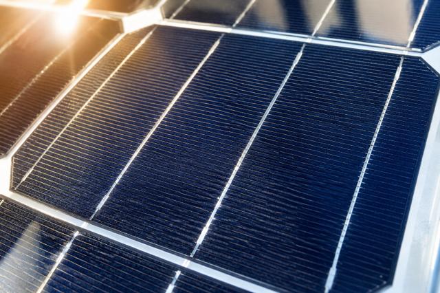
From photon to kilowatt-hour: the physics of a solar cell and the path of energy through a complete PV system.
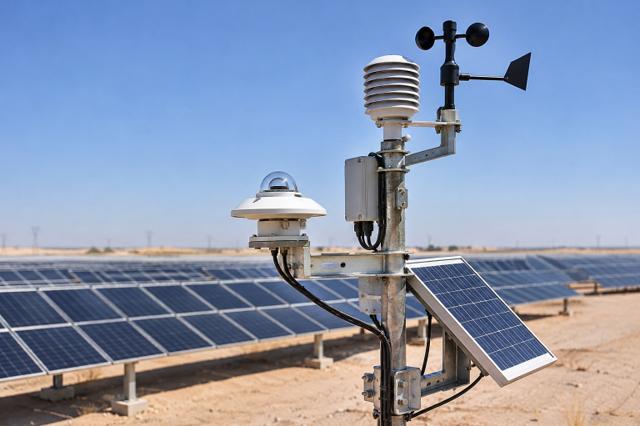
GHI, DNI and DHI explained, how sun position changes through the day and year, and why the Gulf is one of the world's best solar resources.
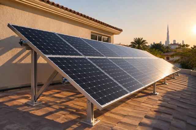
How to orient a PV array: the latitude rule of thumb, why lower tilts often win in the Gulf, and how east–west layouts trade yield for density.
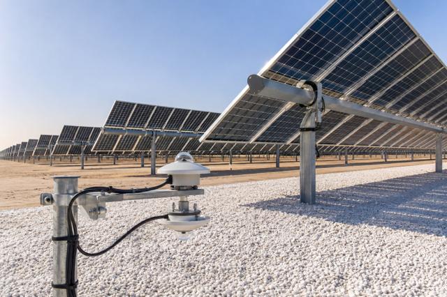
How bifacial modules harvest reflected light, what albedo values to expect on sand, gravel and white membranes, and why bifacial pairs so well with trackers.
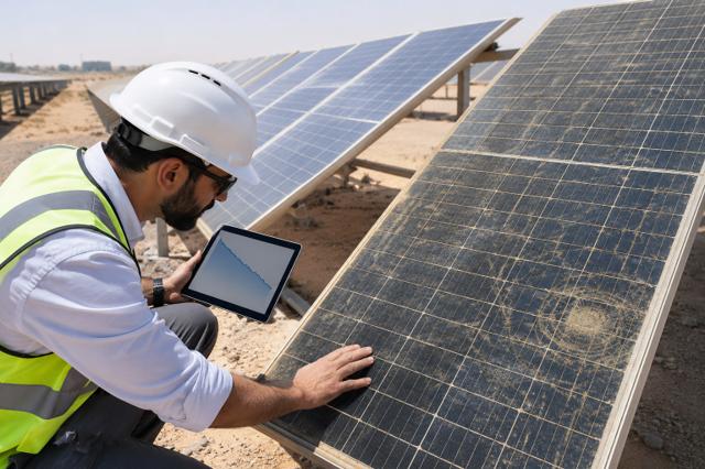
LID, LeTID and long-term power loss explained, and how to read a 12-year product / 30-year linear power warranty.
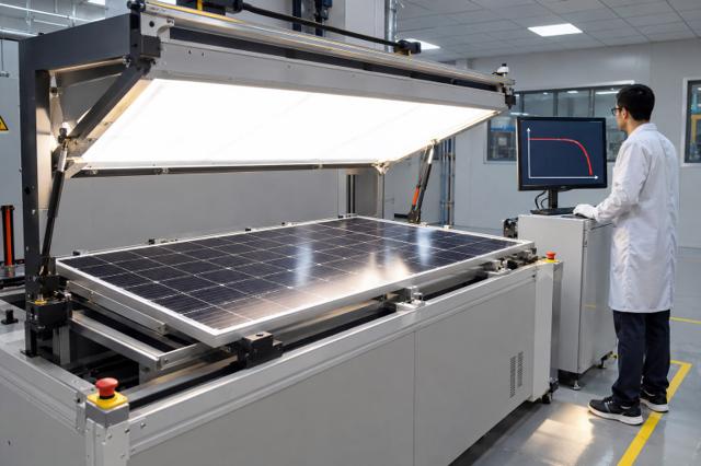
What the datasheet power really means, how temperature coefficients translate into lost watts, and why heat is the main derating factor in the desert.
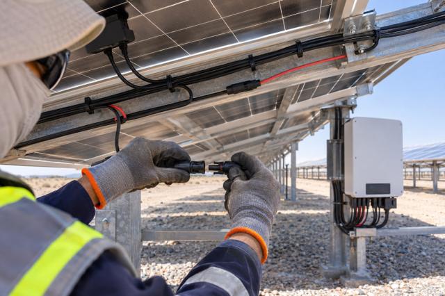
How many modules can go in one string: the cold-temperature Voc limit, the MPPT window and current limits, with a worked 1,500 V example.
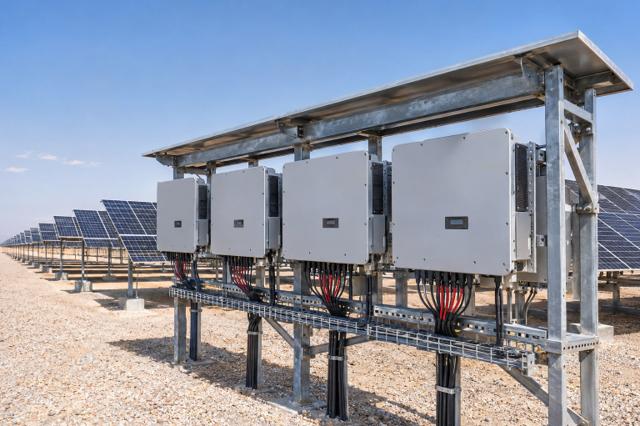
Why PV plants are built with more module power than inverter power, and how to choose a DC/AC ratio between 1.1 and 1.35 without losing too much energy to clipping.
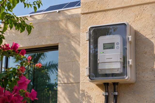
How grid-connected rooftop systems are credited for the electricity they export, and how the tariff scheme changes the right system size and the payback period.
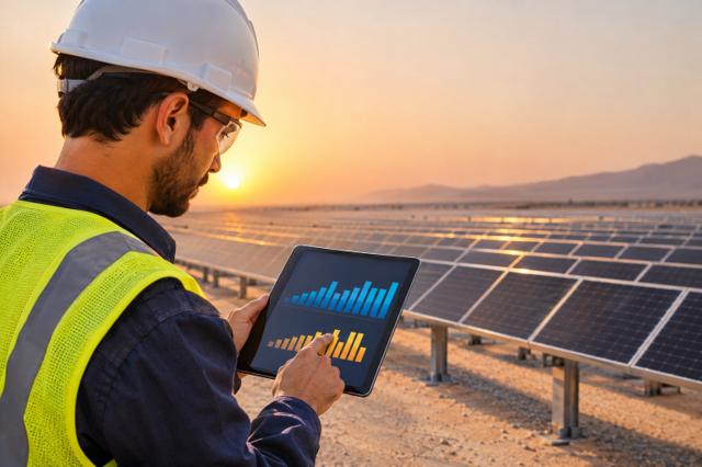
The single number used to compare power plants: lifetime cost divided by lifetime energy, both discounted. What drives it, and why Gulf solar tariffs are among the lowest in the world.
