How shadows reduce PV output far more than their size suggests, how to set row pitch with the ground coverage ratio and the winter-solstice rule, and how bypass diodes and half-cut cells limit the damage.
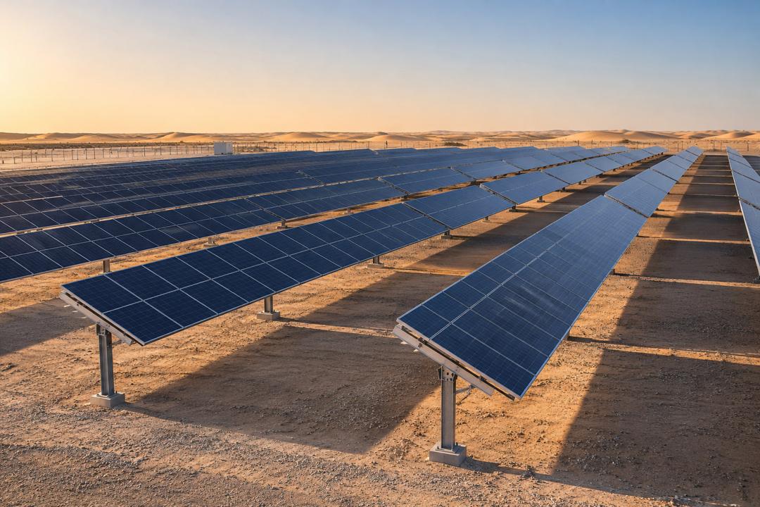
Solar cells in a module are connected in series, so the current of a whole string is limited by its weakest cell. A shadow covering a few cells, from a parapet, a chimney, a water tank, a neighboring row or even a bird dropping, can reduce the output of a module by a third or more. Shading losses are therefore highly non-linear, and avoiding them is one of the first tasks of any layout.
Modules contain bypass diodes, typically three per module, each protecting one sub-string of cells. When part of the module is shaded, the corresponding diode conducts and the current flows around the shaded section, preventing hot spots and keeping the rest of the module producing. Half-cut cell modules go further: they are wired as two parallel halves, so a shadow across the bottom edge (the most common pattern of inter-row shading) removes only part of the module’s output. Module-level power electronics (optimizers or microinverters) can further reduce mismatch on complex roofs.
In ground-mounted and flat-roof plants, the key parameter is the row pitch, usually expressed through the ground coverage ratio (GCR = module collector width ÷ row pitch). A high GCR packs more kWp on the land but increases mutual shading in the morning, evening and winter; a low GCR wastes land and cable length. Fixed-tilt plants in the Gulf commonly use a GCR of 0.40–0.50, single-axis trackers 0.30–0.40 with backtracking to avoid row-to-row shading.
A classic design rule is to keep rows shade-free between roughly 9:00 and 15:00 solar time on the winter solstice (21 December in the northern hemisphere), when the sun is lowest. The minimum gap is d = h ÷ tan(α) × cos(γ), where h is the height difference between the top edge of one row and the bottom of the next, α the solar elevation and γ the solar azimuth relative to the row normal. At latitudes around 24–25° N, typical of the UAE, the low winter sun still allows fairly tight spacing compared with Europe.
Because energy, land and cable costs interact, the final pitch is usually optimized with simulation software that models 3D shading, electrical mismatch and the diffuse light reaching bifacial rear sides. On rooftops, a shading survey (sun-path diagram or drone model) should also map obstructions such as parapets, HVAC units and future buildings before the layout is frozen.
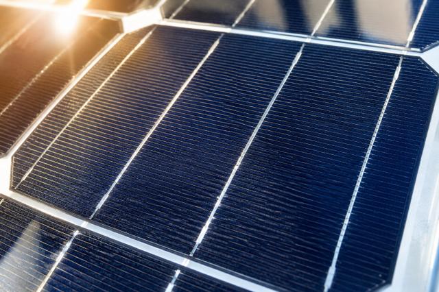
From photon to kilowatt-hour: the physics of a solar cell and the path of energy through a complete PV system.
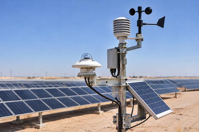
GHI, DNI and DHI explained, how sun position changes through the day and year, and why the Gulf is one of the world's best solar resources.
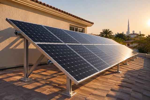
How to orient a PV array: the latitude rule of thumb, why lower tilts often win in the Gulf, and how east–west layouts trade yield for density.
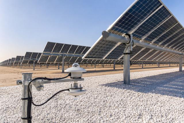
How bifacial modules harvest reflected light, what albedo values to expect on sand, gravel and white membranes, and why bifacial pairs so well with trackers.
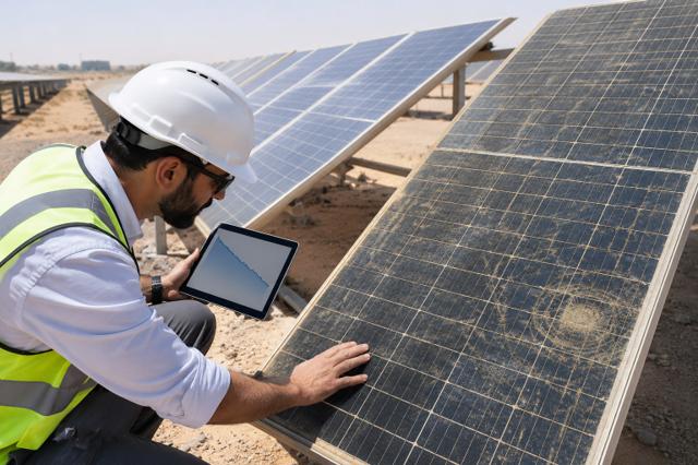
LID, LeTID and long-term power loss explained, and how to read a 12-year product / 30-year linear power warranty.
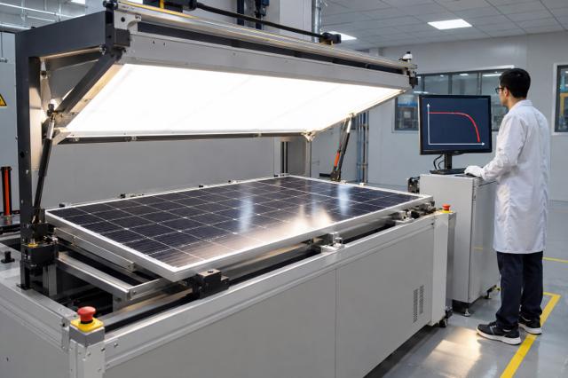
What the datasheet power really means, how temperature coefficients translate into lost watts, and why heat is the main derating factor in the desert.
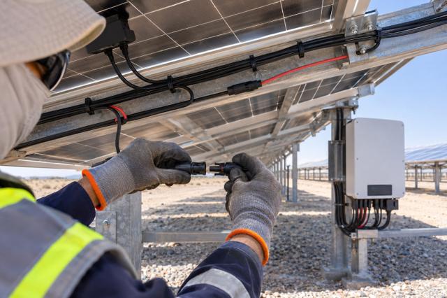
How many modules can go in one string: the cold-temperature Voc limit, the MPPT window and current limits, with a worked 1,500 V example.
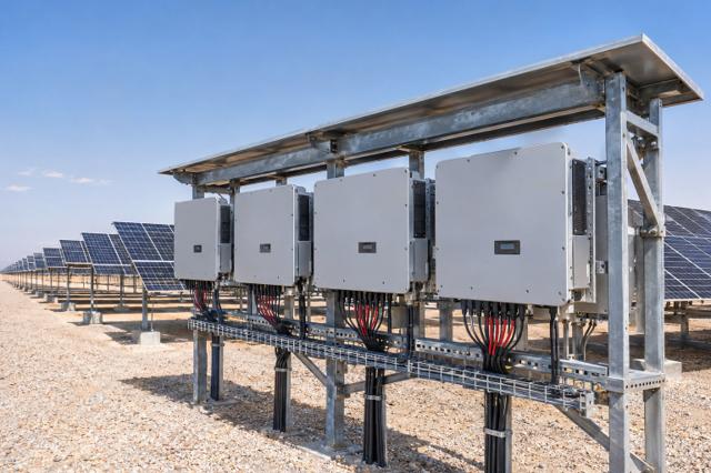
Why PV plants are built with more module power than inverter power, and how to choose a DC/AC ratio between 1.1 and 1.35 without losing too much energy to clipping.
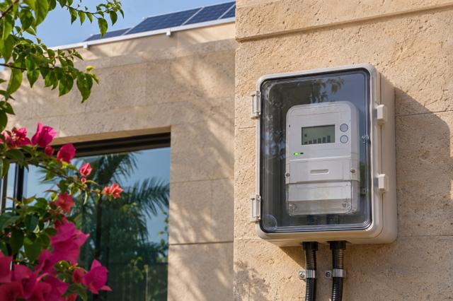
How grid-connected rooftop systems are credited for the electricity they export, and how the tariff scheme changes the right system size and the payback period.

The single number used to compare power plants: lifetime cost divided by lifetime energy, both discounted. What drives it, and why Gulf solar tariffs are among the lowest in the world.
